To identify the perfect connector, it must meet a series of critical requirements, including current rating, voltage rating, circuit size, mating force, wire gauge compatibility, construction, termination method, and safety features, etc.
Now, let’s delve into the critical components of a terminal connector.
How many areas does the terminal connector consist of?
A terminal is mainly composed of three zones: Mating zone, transition zone, and crimp zone (see Figure A). These zones are crucial for understanding the connector performance.
As the name suggests, the mating zone is where the terminal interfaces with its counterpart. It is meticulously designed by connector engineers to ensure smooth engagement with mating terminals and reliable electrical contact. Any deformation in this zone during the crimping process will severely affect the connector performance.
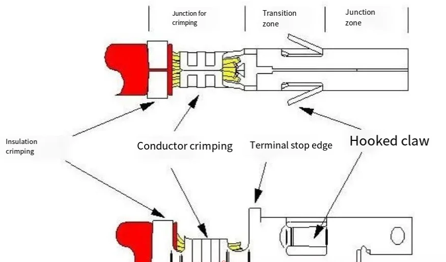
The transition zone is also carefully engineered to remain stable during the crimping process. Random modifying the position of spring tabs or terminal stops will affect the connector performance.
The crimp zone is the only section designed to deform in the crimping process. It is recommended to use the terminal equipment specified by the connector manufacturer to clamp the crimp zone, ensuring a secure connection with wires. Ideally, all wire crimping operations should be confined to the crimp zone exclusively.
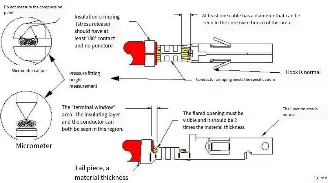
A proper crimp example is illustrated in Figure B. During the crimping process, the insulation crimp compresses the insulation layer without penetrating it. The wire strands (or brush) should extend beyond the front of the conductor crimp by at least the wire conductor’s diameter. For example, for a 1.02 mm (18 AWG) cable, the overhang length should be at least 0.40″. Between the insulation crimp zone and the conductor crimp zone, we can clearly see both the insulation layer and the conductor. The conductor crimp zone features flared openings at both entry and exit ends, while the transition and mating zones maintain consistent form before and after crimping.
If the shape of your crimped terminal differs from that shown in Figure B, this usually indicates a certain error occurred during the crimping process. Next, we will examine 13 common issues that may be encountered in the crimping process and share corresponding preventive measures.
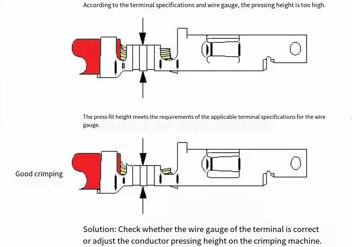
The primary issue is insufficient crimp height.
Crimp height, which refers to the cross-sectional height of the conductor crimp zone upon completion of the crimping, is a critical indicator for ensuring proper crimping. Connector manufacturers have preset specific crimp heights for terminals based on different wire sizes. Sometimes, the proper crimp height range or tolerance can be as precise as 0.002″. Therefore, under such stringent specifications, ensuring the accuracy of crimping machine settings becomes particularly crucial.
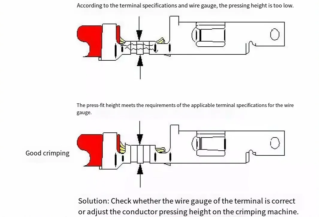
Either insufficient or excessive crimp height will affect the specified crimping strength, meaning the terminal’s grip on the wire. This impact will further reduce the wire’s pull-out force and rated current, often leading to degraded performance of the crimped connection under non-optimal working conditions. Specifically, insufficient crimp height may actually cut the wire strands or fracture the metal in the conductor crimp zone. Conversely, excessive crimp height fails to properly compress the wire strands, resulting in too many ineffective voids in the crimp zone, thereby reducing metal-to-metal contact between the wire strands and terminal metal.
Excessive backward crimp height
The solutions to Issues #1 and #2 are quite straightforward: Simply adjust the conductor crimp height on the crimping machine. When operating the crimping machine for the first time, always use a vernier caliper or micrometer (as shown in Figure B) to confirm that the crimp height falls within the specified range. Additionally, regular rechecks during work are necessary to ensure the crimp height remains correct.
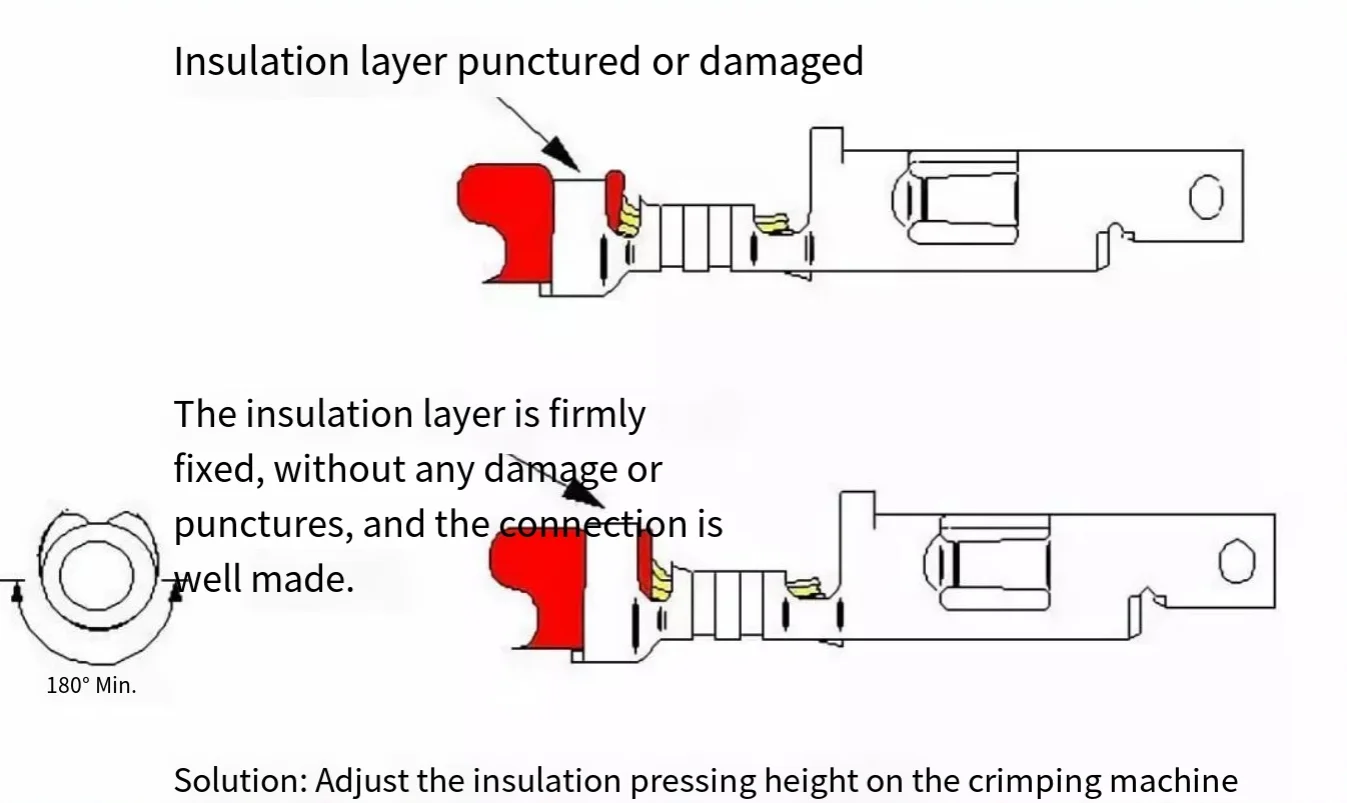
Insufficient insulation crimp zone
It is worth noting that due to the diversity of insulation types and variations in thickness, connector manufacturers typically do not provide specific recommendations for insulation crimp height. However, the insulation crimp is crucial for the conductor crimp zone, as it provides the necessary stress relief to prevent wire breakage when the cable is bent. If the insulation crimp zone is too small, metal stress will become overly concentrated in this zone, compromising its effectiveness of stress relief function.
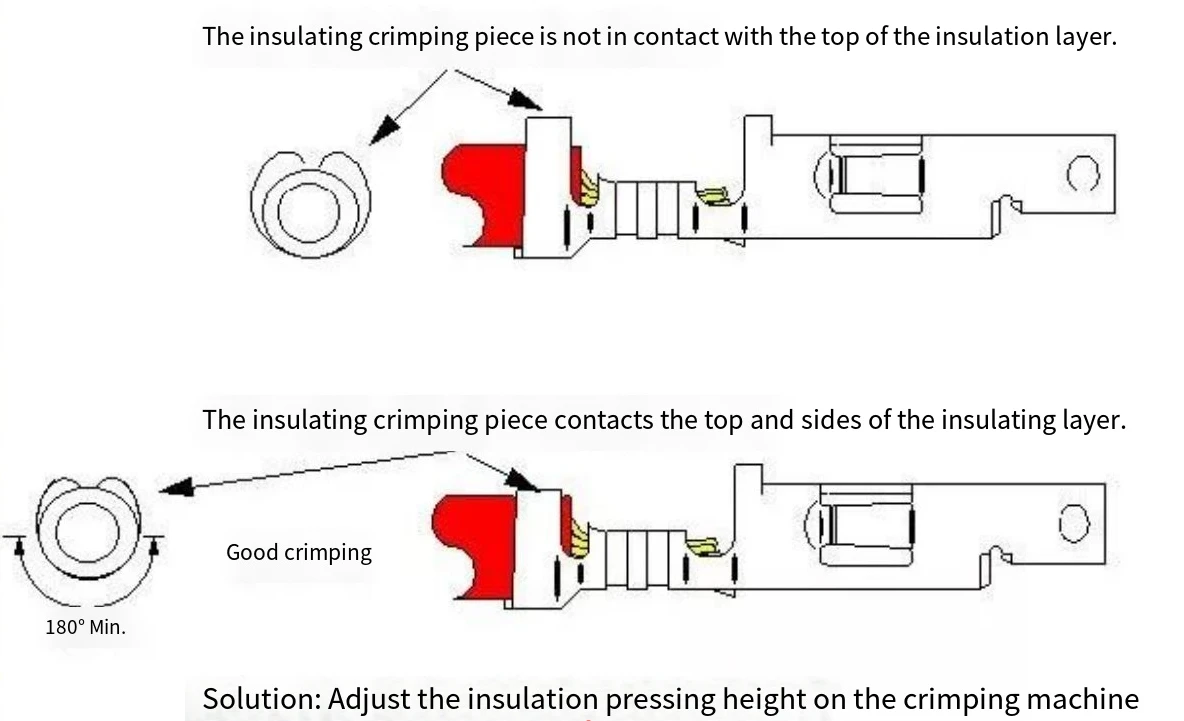
Excessive insulation crimp zone
If the insulation crimp zone is too large, it may trigger the risk of wire breakage when the cable is bent. Moreover, an excessively large insulation crimp zone can affect the overall dimensions and mechanical performance of the connector. Therefore, during operation, it should be ensured that the insulation crimp zone is controlled within an appropriate range to guarantee the cable stability and connector performance.
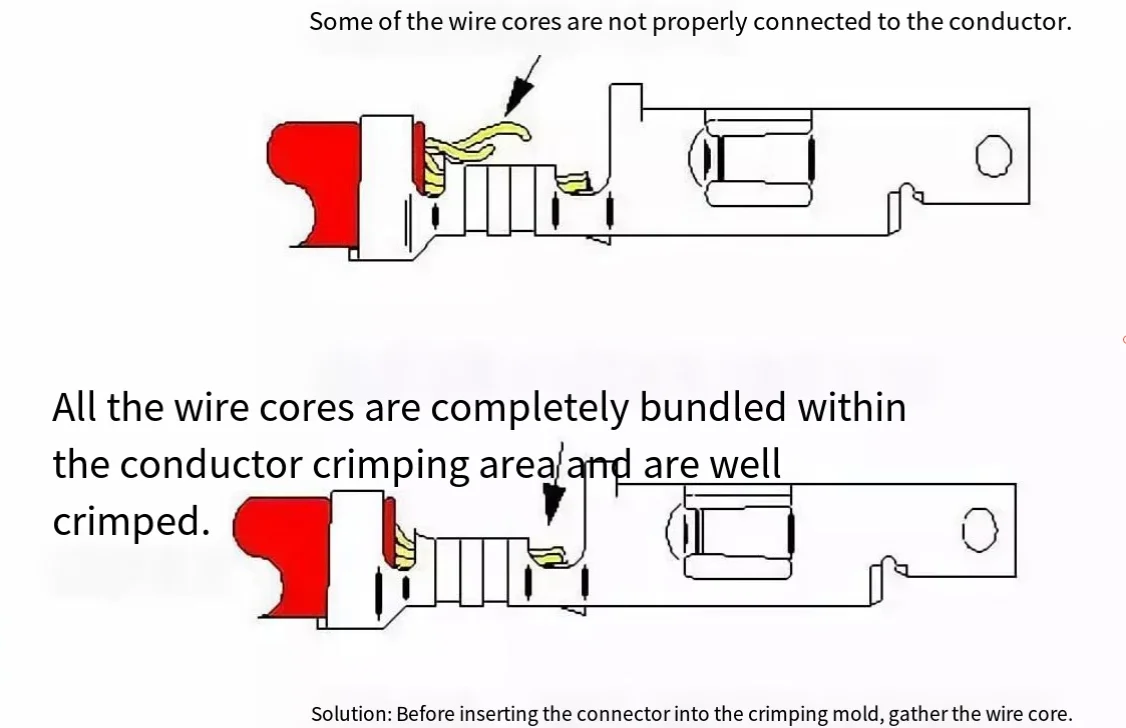
Loose wire strands
Loose wire strands are a common issue during the crimping process. When the strands are not fully enclosed within the conductor crimp zone, the strength and current-carrying capacity of the crimp are significantly reduced. To ensure a proper crimp effect, the crimp height requirements specified by the connector manufacturer must be followed. If some wire strands fail to meet the required crimp height or strength, the overall performance of the crimp will not meet specifications.
Typically, the issue of loose wire strands can be resolved by simply re-gathering the cable and inserting it into the terminal. However, when handling or bundling cables, strands may accidentally separate. To avoid this, a strip-and-hold process can be adopted, where the insulation is fully removed only just before crimping, which can help reduce wire strand loosening to some extent.
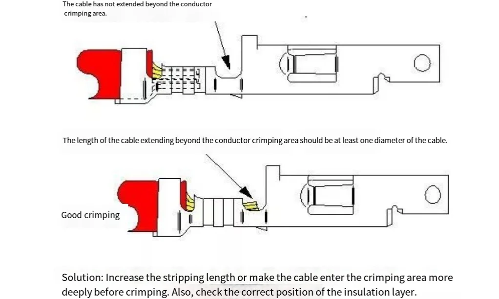
Insufficient strip length
If the strip length is too short or the cable does not fully enter the conductor crimp zone, the termination may fail to achieve the intended pull-out force due to reduced metal contact area between the cable and the terminal. When the strip length of the cable is insufficient (while ensuring the insulation layer is correctly positioned), the distance the cable extends beyond the front of the conductor crimp zone will not meet the required one-cable-diameter standard. To resolve this issue, simply adjust the strip length on the stripping equipment to the standard required for the terminal.
Over-insertion of cable
When the cable is inserted too deeply into the crimp zone, a series of issues can arise. In particular, if the insulation layer is pushed too far into the insulation crimp zone, the conductor may extend into the transition zone, which can lead to three different failure modes in actual practice. Two of the three failure modes are related to reduced metal-to-metal contact in the conductor crimp zone, directly affecting the rated current and cable pull-out force. Additionally, metal-to-plastic contact is weaker than metal-to-metal contact and is non-conductive.
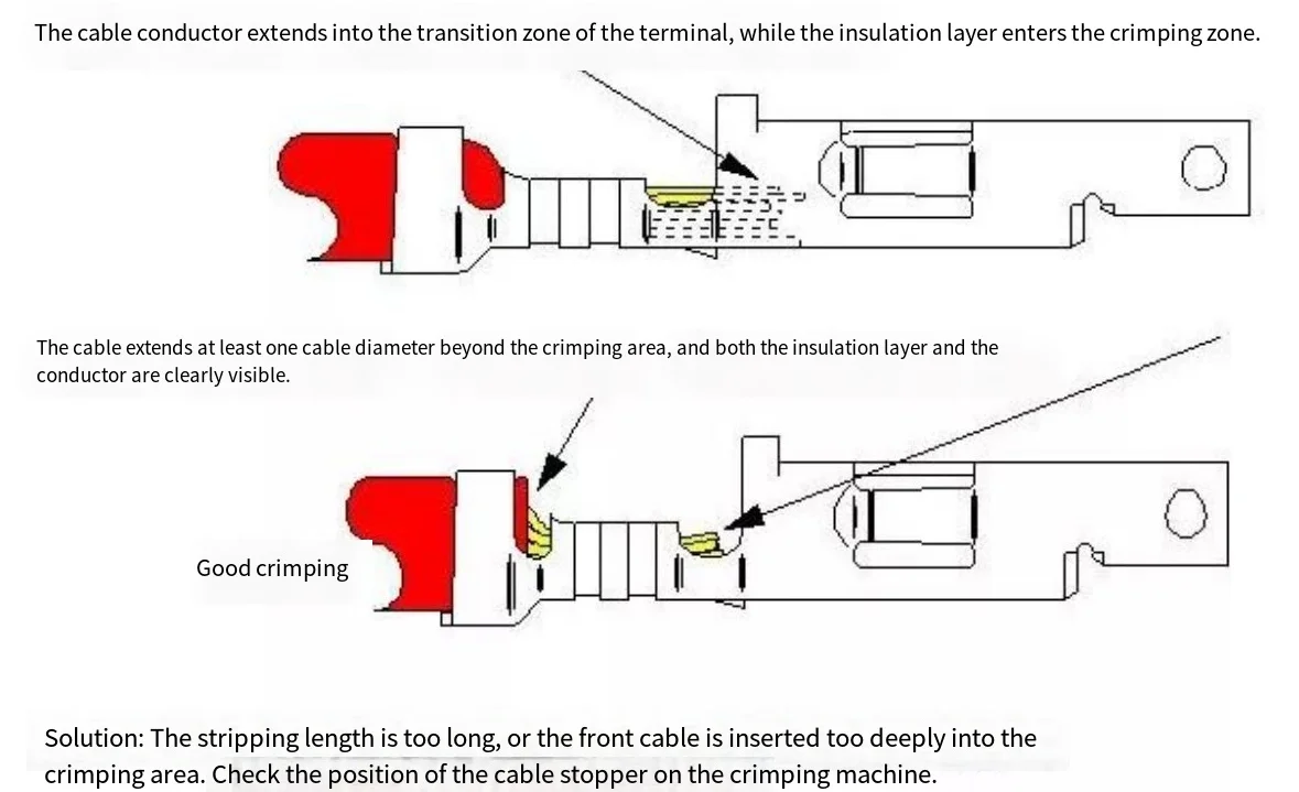
The third failure mode may occur during connector mating. If the cable extends too deeply into the transition zone, the tip of the pin terminal may collide with the cable, preventing the connector from fully seating or even causing the pin or socket terminal to bend – a condition known as terminal collision. In extreme cases, even if the terminal is fully seated within the housing, it may be pushed out from the back of the housing. To resolve this issue, one should ensure that excessive force is not applied when inserting the cable into the crimping machine, to prevent the cable from overshooting the cable stop of the crimping machine; alternatively, adjust the position of the cable stop so that it can correctly axially position the stripped cable.
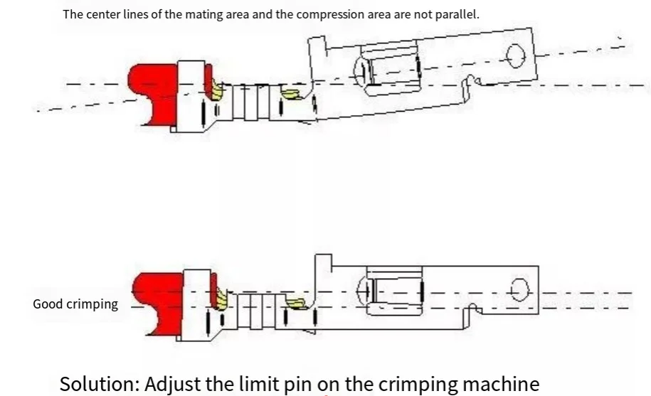
Another issue is the “banana-like shape” crimp. Due to the banana-like shape of the crimped terminal, it becomes difficult to insert into the housing and may cause terminal collision. To resolve this issue, simply adjust the position of the limit pin on the crimping machine. This pin is located in the crimping machine and contacts the mating zone of the terminal when the crimp zone is crimped onto the cable. During crimping, a significant amount of metal at one end of the terminal moves within the crimp zone, and this force often causes the front of the terminal to lift. Proper use of the “limit pin” can prevent the occurrence of such lifting.
Excessively forward crimp position
A relatively noticeable crimping issue lies in localized damage to the transition zone. In the illustrated terminal diagram, those vertical protrusions are referred to as “terminal stops”, designed to prevent the terminal from being inserted too deeply into the housing. However, if the stops are completely compromised, the actual terminal may be pushed into the back of the housing.
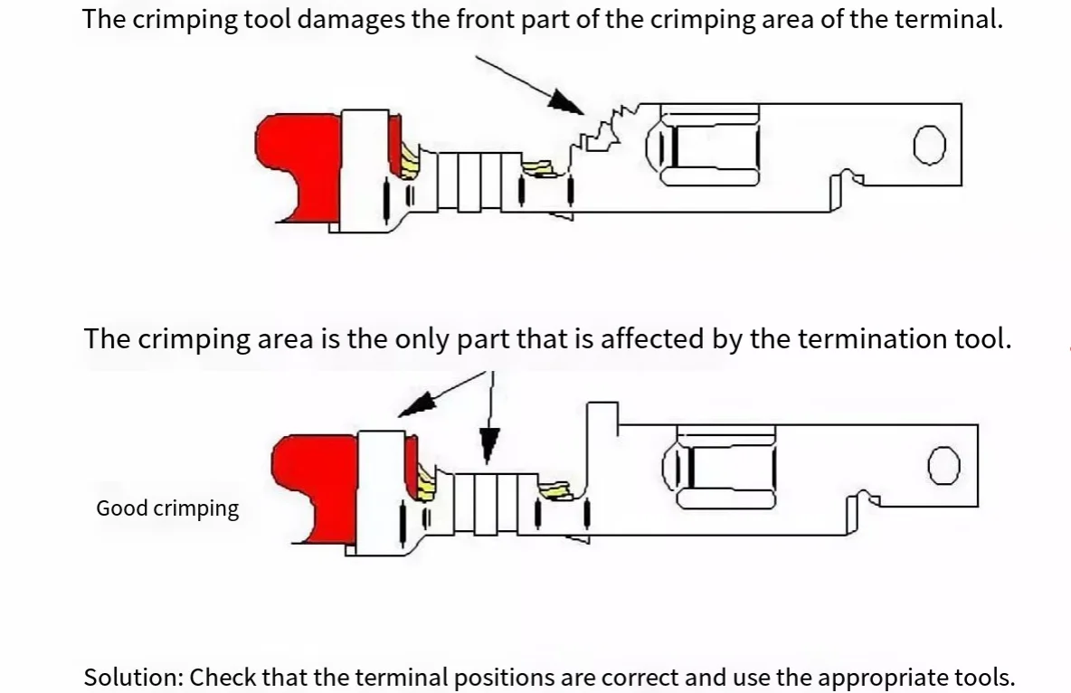
The solution is relatively straightforward: This typically occurs due to misalignment between the terminal and the metal strip in the crimping machine. By loosening the interchangeable tool’s basal plate and realigning the crimping machine, this issue can be easily resolved.
Next, we will explore another potential issue: The flared mouth is too small.
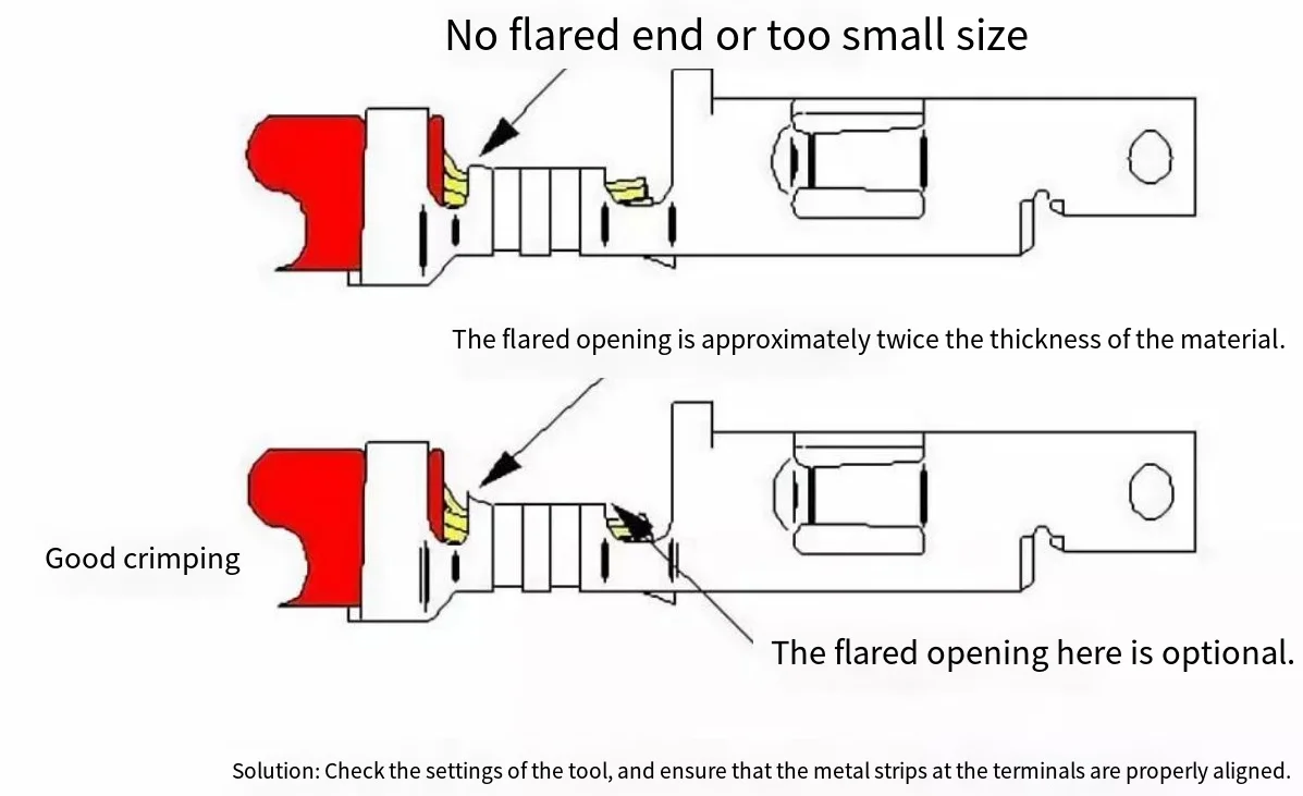
The size of the flared mouth is critical – it should approximate twice the thickness of the terminal material. For example, for a terminal with a thickness of 0.008″, the flared mouth should measure around 0.016″. While minor deviations may not significantly impact terminal performance, an undersized or missing flared mouth can sever wire strands, reducing the connection strength of the terminal. To address this issue, it should be ensured that the alignment between the punch and anvil in the crimping equipment is precise.
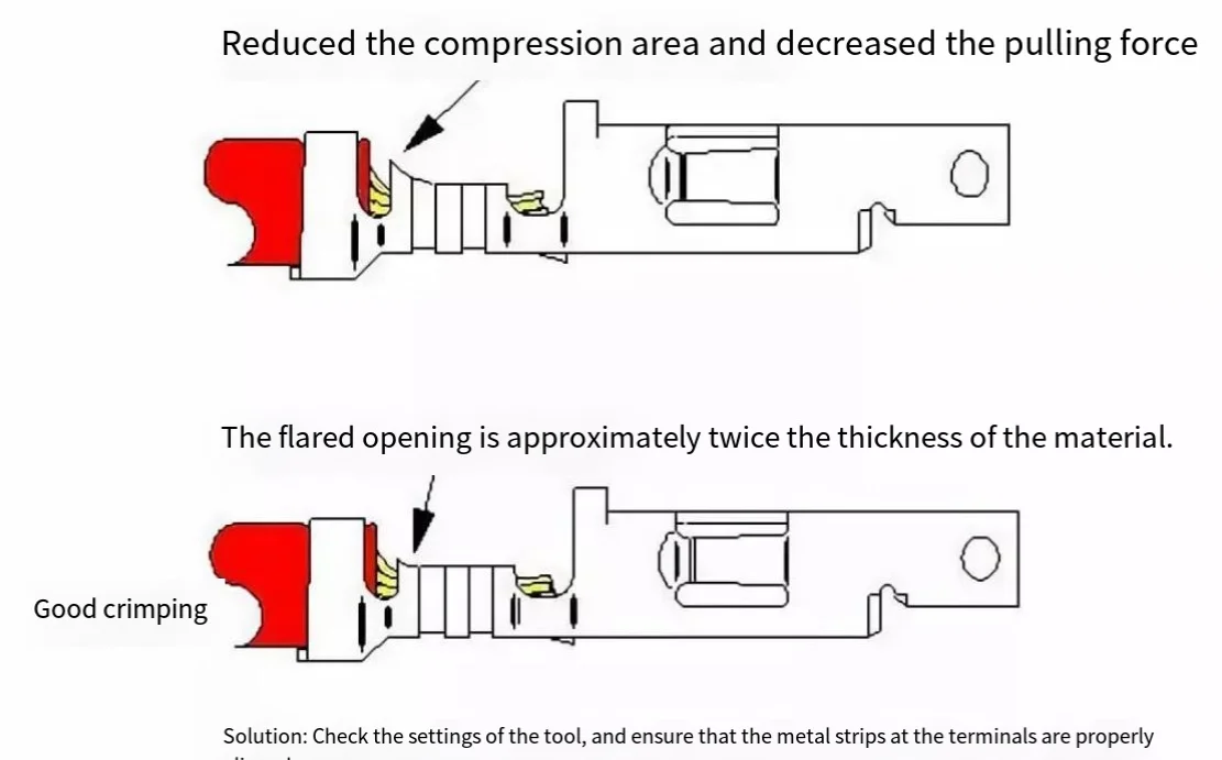
Conversely, an excessively large flared mouth can also pose issues. An oversized flared mouth reduces the contact area between the terminal crimp zone and the cable, thereby diminishing pull-out strength. If the crimp height is correct, the issue might be caused by tool wear, necessitating tool replacement.
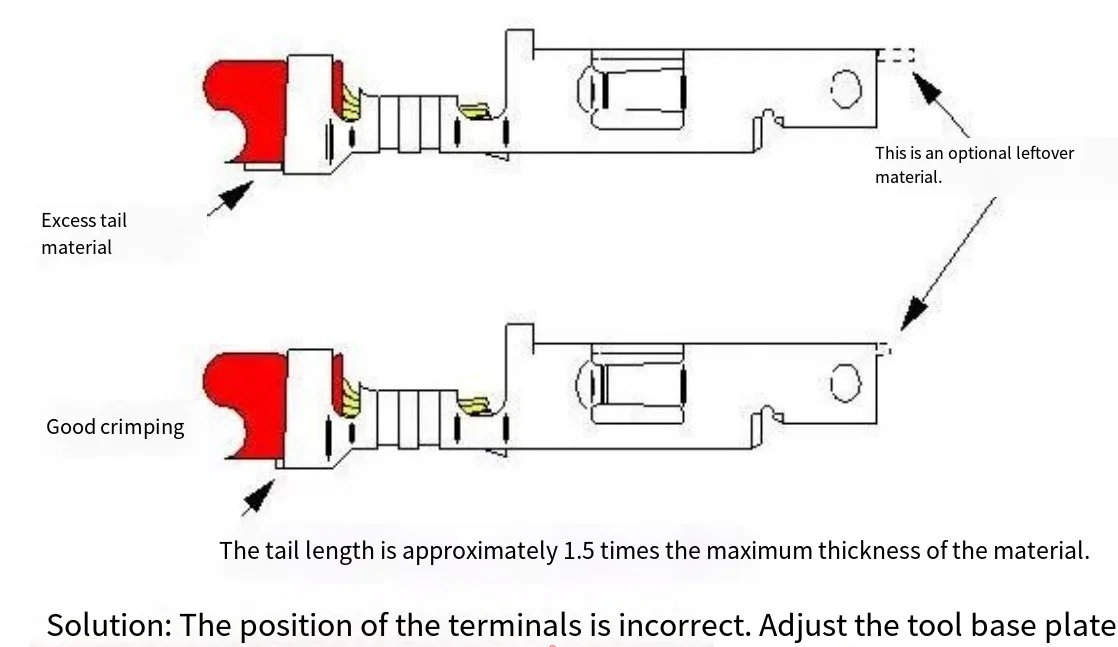
Excessive tail length
Upon completion of the crimping, the excess tail is trimmed from the terminal. If the tail is left too long, a series of issues may arise. When the terminal is inserted into the housing, the protruding metal tail can extend beyond the rear of the connector, potentially causing arcing between adjacent contacts under high voltage. Additionally, an excessively long tail at the front of the terminal may interfere with proper connector mating or even trigger “terminal collision”.
Excessive tail length
Upon completion of the crimping, the excess tail is trimmed, but if too much length is retained, it can cause a series of issues. An excessively long tail may protrude from the rear of the connector when the terminal is inserted into the housing, potentially leading to arcing between adjacent contacts under high voltage. Additionally, an excessively long tail at the front of the terminal may interfere with proper connector mating or even trigger “terminal collision”.
The solution is relatively simple: Adjust the basal plate on the crimping machine to ensure the terminal is accurately centered. If the terminal is not properly centered, the flared mouth may not form correctly, which is often related to the spatial relationship between the flared mouth and the tail tool.
Barb bending
Although barb bending may not be directly caused by improper crimping, it can affect the connector performance. The barb may bend excessively inward or outward, preventing the terminal from fully locking into the plastic housing. This damage may result from various causes, including excessive tension on the crimping machine’s reel holder friction wheel or inadvertent mishandling during transportation after the terminal has been crimped onto the cable. Additionally, barbs may bend due to improper handling during cable bundling or when extracting individual terminated wires from the harness.
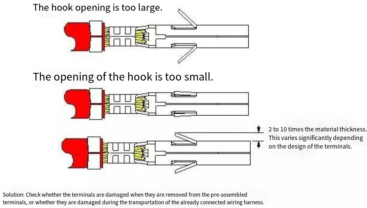
If the damage occurs during the crimping machine operation, the tension of the friction wheel should be adjusted to ensure the terminal reel does not unwind under its own weight. If the issue stems from the cable bundling process, using smaller harnesses or optimizing the handling procedures should be considered.
Continue Reading
How to Analysis Terminal Material and Welding Process?
How Many Types of Electrical Terminals and Connector?(Guide for 14 Types)
Connection Methods and Analysis of Terminals and Connectors(5 Necessary Steps)
Electrical Terminal Materials: 4 Key Points (+How to Select?)
How many types of connector and terminal insulation materials(3 major categories)?
What factors determine the cost of electrical terminals and connectors? (10 Key Factors)